|
U-505 Control Room Planesman Stations |
|
We are now facing the starboard side of the control room: the planesmans' stations.
At the very right of the photo below is the ladder to the conning tower. Behind us is the
chart table.
The planesmen - Rudergänger - were the operators of the boat's hydroplanes. Hydroplanes are to a U-boat what elevators are to an aeroplane. A U-boat has planes at the bow and the stern. They are used to dynamically control the angle of the boat, and therefore usually whether it rises or sinks. By dynamic control we mean that the boat has to be moving for the planes to have any effect, just as a boat's rudder only works when the boat moves. To get the boat to dive, the forward plane was tilted down slightly and the aft plane was tilted up slightly. Of course tanks had to be flooded too, but the planes helped the boat to start 'driving' down at the right angle. Apart from helping the boat to dive, the planes could also help drive the boat to the surface. Furthermore the planes help the boat to maintain periscope depth - together with the trimming tanks they keep the boat level in pitch. Skillful operation of the planes was absolutely critical to submerged attacks. The job is particularly difficult because it involves a sense of how the boat is moving that is best described as 'seat of the pants'. The job requires anticipating the next adjustment rather than just chasing the boat's angle indicators. The Chief Engineer often stood behind planesmen to coach them on the required amount of input. However during a submerged attack, the boat's best planesmen took over no matter if it was their watch or not. These specialist planesmen were highly valued and were called Gefechtsrudergänger. |

|
|
At the top of the photo, above the planesmen's stations are two large dials. The one on the right is the depth meter, marked
off in individual meters it shows how much water lies above the boat. Above and between the plane controls is a large vertical
gauge which shows the periscope elevation, important for knowing if too much of the periscope is protruding above the surface.
Each planesman sits on a seat before the controls. At first glance it appears that a plane is operated by the large wheel in front of the planesman, yet this is only half the story. Most of the time he used the two large buttons that are situated on top of the box in the centre of the wheel. These buttons operated the plane via an electric motor. The longer a button was pressed, the further the plane tilted in the corresponding direction. You can see the plane angle guages directly above each planesman's control. The large wheel for each plane was used as a manual backup. It was required for silent running as the electric motors that normally controlled the planes made a noise that could be detected by the enemy. Furthermore the wheel was needed if the electrical system failed. The wheel is large as this helps get more muscle into the movement - at times a couple men needed to strain at the wheel if the plane had become damaged. You can clearly see the chain that is moved by turning the wheel. To the left of the forward planesman's control is a large upright cylinder seated on the deck. This is the gyrocompass. This electro-mechanical device is required because in a steel boat normal magnetic compasses are unreliable. A gyrocompass works by keeping a ball spinning at high speed, and the gyroscopic effect of the of the spinning ball imparts stability and therefore a steady position, much like a magnetic needle maintains its position. However all gyrocompasses are susceptible to 'drift' and need to be calibrated regularly. Since a gyrocompass is an electro-mechanical device its readout can be 'repeated' via wires to various parts of the boat as we have seen already. |
 |
|
In the close-up above you can see the manufacturers of the hydroplane control system are Brown, Boveri and Cie - they have stamped
BBC into the centre of the control box. Notice too that the planesman is provided with two grips mounted on top of this box. There were times
when these were needed as if the boat took on a severe angle - a frequent occurrence - it was unwise to hold on to the wheel for obvious reasons.
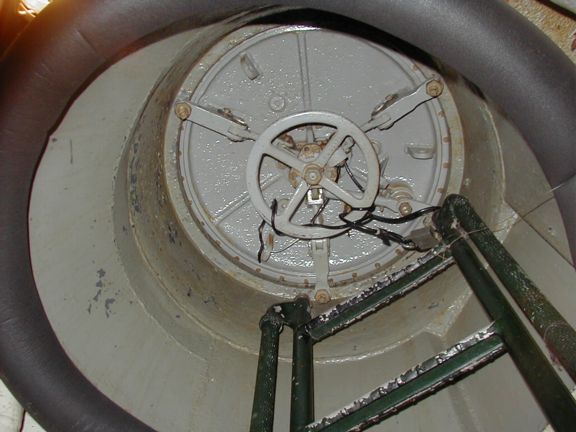
To the right of the aft planesman's control you can see the controls for trimming the boat. These were only operated by the Chief Engineer. These controls were used to adjust the amount of water in various trimming tanks. Trimming tanks were needed because as supplies were used and torpedoes spent, the weight of the boat changed in places and therefore the point of balance shifted. Trim tanks compensated for the changing balance point of the boat. This was such a sensitive adjustment that even a couple men moving from forward to aft could put the boat out of trim. As mentioned earlier to the right (aft) of this planesman's station is the ladder to the conning tower. Below is the view up this ladder to the closed hatch. Note that the black cable wound around the catch is not original - it is a security measure by the museum. During a crash dive the men from the bridge did not 'climb' down the ladder into the control tower and then down this ladder. Rather they jumped down through the hatches, using the ladders only as a guide. There was not enough time for each man to carefully use each step - it was each man down as fast as he could, and if the man that had gone before lingered too long he got a boot on his head or a crushed hand as a reminder to be faster next time. |
 |
All photos are for personal viewing only and remain
© David Speaks. All rights reserved.
![]()